
Green Energy: Battery Energy Storage Systems
Overview

The growth in renewables such as wind and solar energy generation has led to an increased demand for battery energy storage systems (BESS) within the various energy industry segments: residential, industrial, and utility. Homes and businesses are generating solar power, and the demand to store that energy through battery energy storage systems is increasing.
European residential solar and storage soared by 44% to 140,000 installed units in 2020. And not surprisingly, the household solar forecast for the coming years continues to look bright, with European solar and storage set to grow by more than 400%, from 3 GWh installed storage capacity in 2020 to 12.8 GWh in 2025.
The role of relays in Battery Management Systems
Battery management systems (BMSs) monitor temperature and voltage in battery pack cells to guarantee safety and reliability. More specifically, these systems keep tabs on voltage, current, and temperature limits and control the disconnect relay. This allows them to disconnect themselves from the external application in case of malfunction.Consider this example: A BMS communicates via an interface to the external application that a cell is getting too hot, meaning that the battery should not be charged any further. The system controller will need to follow the BMS data and stop charging. If it doesn’t, the battery management system needs to disconnect independently from the external application.
In this situation, the BMS need to activate the relay, cease operation, and trigger a fault.
Functions of BESS
- Charge
During daylight, the battery storage system is charged by clean, solar-generated electricity. - OptimizeIntelligent battery software uses algorithms to coordinate solar production, usage history, utility rate structures, and weather patterns to optimize when the stored energy is used.
- Discharge
Energy is discharged from the battery storage system during times of high usage, reducing or eliminating costly demand charges.
FCL Components' recommended relay for battery storage systems
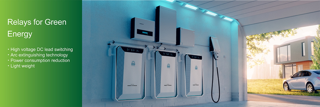
FCL Components' FTR-E1 high voltage DC relay is a versatile relay available in four different types. Two innovative relay technologies have been used the design the FTR-E1 relay.- Arc extinguishing
The current direction of the battery storage is reversed during charging/discharging. There is no difference in arc space dependent on the current direction. This ensures the same performance when charging and discharging.
Learn more about arc extinguishing. - Power consumption reduction
Power consumption reduction by holding voltage method: Key benefit: contributes to ease in temperature design and reduction in PCB design cost.
Holding voltage drive method:
The voltage applied to the coil can be reduced to 50% of the rated voltage.- FTR-E1-MF, GR, HA (20A-800VDC or 30A-450VDC)
The coil power consumption is reduced to about 25% (0.23W) - FTR-E1-HC (60A-400VDC)
The coil power consumption reduced to about 25% (0.3W)
How to shift to holding voltage drive:
Apply 100% of the rated voltage for 100m sec to the coil first, then use 50% of the rated voltage as holding voltage. - FTR-E1-MF, GR, HA (20A-800VDC or 30A-450VDC)
Both technologies allow the FTR-E1-HC to have the smallest size and weight in its class, measuring just 28.3 × 43.6 × 36. mm and weighing just 75g. Size is limited in most applications, and the small size of this relay helps to fit design constraints.
For more information:
BESS LeafletProduct Portfolio
| Applications | Contact Arrangement | Contact Rating | Features | Documentation |
| Battery Energy Storage Systems | 1 Form A | 20A 800VDC 30A 450VDC | Arc cut-off performance No polarity of load side Low power consumption UL certification | FTR-E1 MF/GR/HA |
| 1 Form A | 20A 800VD 30A 450VDC | No polarity of load side Tab terminal | FTR-E1J | |
| 1 Form A | 60A 400VDC 50A 450VDC | No polarity of load side High capacity (60A @60°C, 50A @85°C) UL certification | FTR-E1-HC | |
| Inverter - DC side | 1 Form A | 20A 800VDC 30A 450VDC | Arc cut-off performance No polarity of load side Low power consumption UL certification | FTR-E1 MF/GR/HA |
| 1 Form A | 20A 800VD 30A 450VDC | No polarity of load side Tab terminal | FTR-E1J | |
| 1 Form A | 60A 400VDC 50A 450VDC | No polarity of load side High capacity (60A @60°C, 50A @85°C) UL certification | FTR-E1-HC | Inverter - AC side | 1 Form A | 32A 250VAC | 1.5mm contact gap | FTR-K3-PV |
| 1 Form A | 25A 250VAC | 1.5mm contact gap | FTR-K3-WG | |
| 1 Form A | 32A-250VAC | 1.8mm contact gap | FTR-K3-PS | |
| 1 Form A | 25A-250VAC | 1.8mm contact gap | FTR-K3-WS |
Infographics
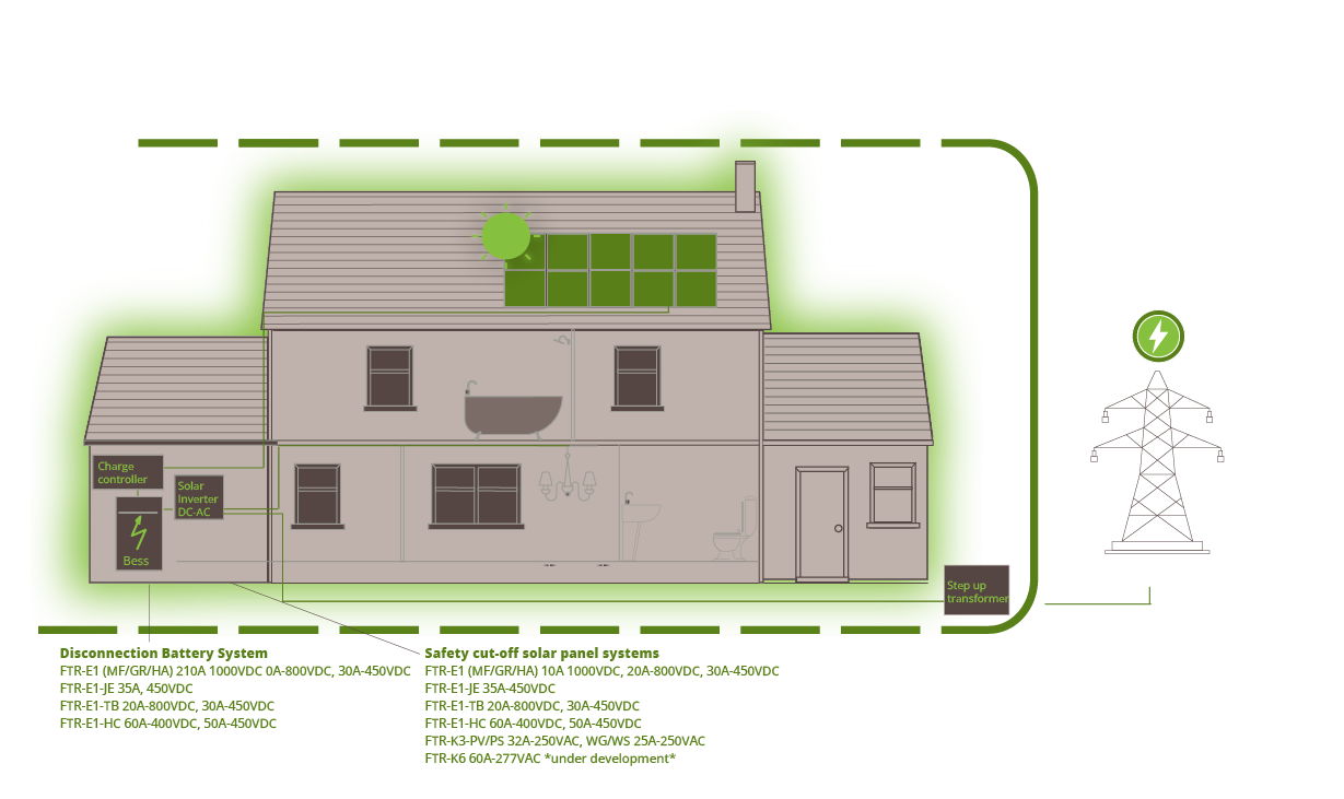
AC coupled
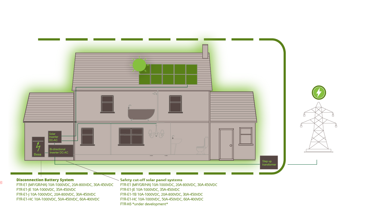
DC coupled
Solution Brief
How FCL Components and Battery Energy Storage Systems Support a Sustainable Future
There is much talk about the importance of embracing renewable energies, but even the biggest proponents of such a transition will admit that there are several challenges that must be resolved first. One of the biggest hurdles is finding a way to address the intermittency of green energy sources like wind or solar. Another is the fact that not all regions are well suited to renewables. Fossil fuels are easily transported; the sun is not.
Given the broad consensus that the world needs to adopt more sustainable energy sources, there is much excitement around the role that could be played by battery technology. This involves not just the batteries themselves, but also supporting software like battery energy management systems, where continued investment is set to swell the global market to $35.14 billion by 2030.
Enabling safe sustainability
Growing demand for battery technology is being witnessed across the board, with residential and corporate use cases being explored worldwide. For instance, the UK is predicted to have over 38GW of energy storage installed by 2050, with battery storage projects expected to play a significant role in meeting net zero objectives.In order to fulfil its promise, battery technology needs to be safe, robust, and reliable. As such, battery management systems (BMS) are being implemented to monitor the temperature and voltage of battery pack cells and, in turn, ensure safe and consistent performance.
BMSs monitor the voltage, current, and temperature limits for a particular battery, controlling the disconnect relay so that batteries can be quickly disconnected should a malfunction occur. If, for example, the BMS identifies that the temperature of a battery cell is too high, it can communicate with the external application and prevent further charging.
A BMSs is also a critical component within any battery energy storage system (BESS), which uses BMS data to activate the battery relay and cease charging when necessary. Additional BESS functionality includes the use of algorithms to optimize charging and reduce costs by discharging energy during times of high demand.
FCL Components: Relays for the battery revolution
With battery technology expected to surge in popularity and a diverse range of projects being pursued, a varied number of relays will be required to facilitate new technologies. At FCL Components, we understand just how important relays are to the correct functioning of BMS solutions.We offer the FTR-E1, a high-voltage DC relay, in four different versions with a contact capability of 20A-800VDC, 30A-450VDC, and 60A-400VDC.