
White Paper: PLC Systems: The Role of Relays

Relay Integration in PLC Systems
Reliable and Safe switching
1. Executive Summary

Programmable Logic Controllers (PLCs) are central to modern industrial automation. Relays—particularly slim-line relays— play a critical role in expanding PLC I/O capability, providing electrical isolation, and enabling safe switching of higher-power loads. This white paper outlines the complete integration process for relays in PLC systems, focusing on relay selection, electrical compatibility, mechanical integration, thermal management, mounting practices, and standards compliance. The goal is to support reliable, compact, and maintainable control panel design. *In this paper, the term ‘PLC system’ includes the PLC, its I/O modules, and the control panel.
2. Role of Relays in PLC Systems
Relays act as an interface between PLC control logic and field devices. Their primary functions include:
- Electrical isolation between low-power PLC electronics and higher-power field circuits
- Voltage and current adaptation between PLC outputs and external loads
- Protection of PLC outputs from overloads, short circuits, and transient voltages
- Simplified maintenance, allowing inexpensive components to fail instead of PLC I/O modules.
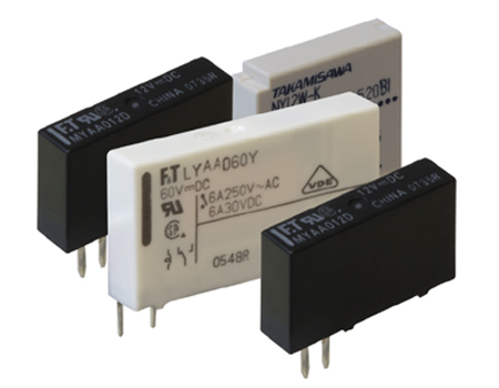
Slim-line relays are particularly well suited to modern panels where space efficiency and modularity are required.
3. Relay Technologies Used with PLC Systems
3.1 Electromechanical Relays
- Physical contacts actuated by an electromagnet
- High isolation and good tolerance to transient overvoltage
- Suitable for inductive and mixed-load applications
- Finite mechanical life
3.2 Solid-State Relays (SSRs)
- Semiconductor-based switching
- Long operational life and silent operation
- Faster switching speeds
- Higher heat generation and sensitivity to leakage current
3.3 Selection Considerations
Electromechanical and solid-state relays are generally preferred over hybrid solutions due to:
- Clearer failure modes
- Simpler thermal behavior
- Easier certification and maintenance
4. Electrical Integration Considerations
Electrical compatibility is the most critical aspect of relay integration.
4.1 Electrical Isolation
Relays provide galvanic separation between:
- PLC outputs (typically 24 V DC logic)
- Field loads (AC or DC, often at higher voltage and current)
- Relays create a galvanically isolated separation, separating the PLC’s 24 V DC logic outputs from AC/DC field loads, that often operate at higher voltage and current levels.
This isolation protects PLC I/O modules from:
- Short circuits
- Ground faults
- Voltage surges from field wiring
4.2 Voltage and Current Matching
Key parameters to verify:
- Coil voltage compatible with PLC output circuits (e.g., 24 V DC)
- Contact rating suitable for load voltage and steady-state current
- Inrush current capability, especially for motors and solenoids.
Relays act as sacrificial elements, preventing damage to PLC output cards.
4.3 Inductive Load Protection
Inductive loads generate high-voltage transients during switching. Recommended protections include:
- Flyback diodes for DC relay coils
- RC snubbers or varistors for AC loads
These measures reduce contact wear, EMI, and PLC disturbances.
4.4 Noise Immunity

Best practices include:
- Physical separation of control and power wiring
- Proper grounding and shielding
- Avoiding parallel routing of low-level signals with high-current conductors
5. Mechanical Integration and Mounting
DIN Rail Mounting
Relays are designed to be plugged into compatible sockets that may mount on 35 mm DIN rails
(IEC 60715), ensuring:
- Interchangeability with standard-compliant relay sockets
- Fast installation and replacement
6. Dimensional Planning
Efficient panel design requires early consideration of relay socket dimensions.
6.1 Key Dimensional Parameters
Relays provide galvanic separation between:
- Width: Determines I/O density on the DIN rail
- Height: Affects vertical rail stacking and enclosure clearance
- Depth: Influences wire bending radius and duct placement
Slim-line relays provide significantly higher channel density compared to traditional relays, enabling space-efficient layouts in various equipment, including control panels and PLC enclosures.
7. Thermal and Environmental Considerations
Relays generate heat, particularly:
- Under high load currents
- When using solid-state relays
Design considerations include:
- Adequate airflow paths
- Avoiding thermal stacking near PLC I/O modules
- Observing temperature derating curves
Environmental ratings (temperature, humidity, vibration) must align with installation conditions.
8. Integration with PLC Systems
8.1 Physical Arrangement
Relays provide galvanic separation between:
- Place relays adjacent to related PLC I/O modules
- Maintain manufacturer-recommended clearances
- Align terminal orientation to reduce wire crossings
8.2 Power Distribution Strategy
- Group relays by voltage level
- Use common power distribution blocks with proper circuit protection
- Clearly segregate AC and DC circuits
9. Maintenance and Lifecycle Considerations
9.1 Relays (relay bodies)
- Relays have predictable wear mechanisms and are inexpensive to replace./li>
- Using relays as interface devices minimizes downtime
- Best practices include:
- Stocking spare relays
9.2 Relay modules (DIN rail mounted bases)
- Best practices include:
- Using status indicators (LEDs) and manual test buttons where available to simplify troubleshooting and functional testing.
- Leaving spare DIN rail capacity
10. PLC systems: safety standards FCL Components relays
Relay shall comply with safety standards such as:
- IEC/EN 61810‑1
– Electromechanical elementary relays - UL 60947-1/60947-4-1
– Low-voltage switchgear and control gear - CSA C22.2 No. 609471/609474-1
– Low-voltage switchgear and control gear - UL 508
– Industrial control equipment - CSA C22.2 No.
– Industrial control equipment
The insulation distances of the relay shall comply with the requirements specified in the standards listed below
- IEC/EN 61010-1/61010-2-201
– Safety requirements for electrical equipment for measurement, control, and laboratory use - UL 61010-1/61010-2-201
– Safety requirements for electrical equipment for measurement, control, and laboratory use
When the relay is used in an explosive gas atmosphere, it is required to comply with the safety standards listed below.
- IEC/EN 60079-0/60079-15
– Explosive atmospheres - UL 121201
– Non incendive electrical equipment for use in class I and II, division 2 and class III, divisions 1 and 2 hazardous (classified) locations - CSA C22.2 No. 213
– Non incendive electrical equipment for use in class I and II, division 2 and class III, divisions 1 and 2 hazardous (classified) locations - ANSI/ISA 12.12.01
– Non incendive electrical equipment for use in class I and II, division 2 and class III, divisions 1 and 2 hazardous (classified) locations
11. Specification Checklist

When selecting relays for PLC systems, verify:
- Electrical ratings (coil and contacts
- Contacts: switching frequency, minimum load, inrush current/power– Coil: power consumption
- Width, height, and depth constraints
- Load type (resistive, inductive, mixed)
- Environmental ratings
12. Conclusion
Proper relay integration is essential to achieving reliable, compact, and maintainable PLC systems. By addressing electrical protection, mechanical layout, thermal behaviour, and standards compliance early in the design phase, engineers can optimize control panel performance while reducing lifecycle cost and downtime. Slim-line relays, when correctly applied, enable high-density automation without compromising safety or reliability.
FCL Components is a Japanese manufacturer of relays with well over 100 years of heritage designing and manufacturing electromechanical relays. These relays are known under the brand names FCL Components (from 2024, before under the name Fujitsu) and Takamisawa.
For more information:
Industrial Relays for Advanced Automation SystemsContact Us